
EDDY DYNAMOMETER provides a sophisticated frictionless, compact and economical solution for your electric motor (engine) testing Laboratory. It is a superior sustitute to brake drum dynamometer, Hydraulic dynamometer and the generator resistance bank sets which are presently used in motor (Engine) Laboratories and production factories.
The EDDY DYNAMOMETER with control panel is suitable for measurement of motor (engine) torque and speed in RPM. It enables you to smoothly control the load applied on the motor (engine) by using a potentiometer. The machine characteristics like overall efficiency and speed/torque characteristics may be determined under vari- ous load and speed conditions.
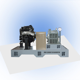
The EDDY DYNAMOMETER consist of an Eddy Current Brake, a Spring Balance, a control panel, and a pulley or flexible coupling to couple the motor (engine) output shaft to the input side of the Dynamometer. The Eddy Dynamometer consists of a drum connected to the output shaft which is locked using a rope connected to the spring balance through a pulley P3. The motor (engine) to be tested is coupled to the dynobrake’s input shaft by a pulley or flexible coupling. There is a component called pole made of ferromagnetic material and having a salient pole struc- ture connected to input shaft. A stationary torroidal coil welded to input side bracket is positioned on the side of the pole. The pole structure with the coil and input shaft is fixed in the input side of the frame, and the cylindrical drum with the output shaft on the output side.
When the coil is energised with the D.C. Supply from the control panel, the pole becomes an electromagnet. The magnetic lines of force emanating from the pole crosses over to the drum and the frame cutting across the airgaps and completes over to the drum and the frame. there will be a concetration of flux near the salient poles and the flux density will be a less in the gaps. When the motor (under testing) rotates, the pole is forcibly rotated. The flux density associated with any point ‘A’ on the drum changes because of the rotation of the pole and an emf is induced in the drum due to this variation in flux density. Since the drum is a block conductor, eddy currents are induced in closed loops inside the drum. By Lenz’s law of electromagnetism, induced current and the resultant magnetic field will try to oppose the very cause producing it. The cause is relative velocity between the pole and the drum. The drum tries to catch up with the pole. But since the drum is locked using a rope through a pulley (P3) and spring balance, the drum cannot rotate. But the torque transmitted by the motor, through the pole to the drum magneti- cally, may be read on the spring balance.